Products
5-in-1 Cellular and W-Fi Antenna System with GPS Receiver
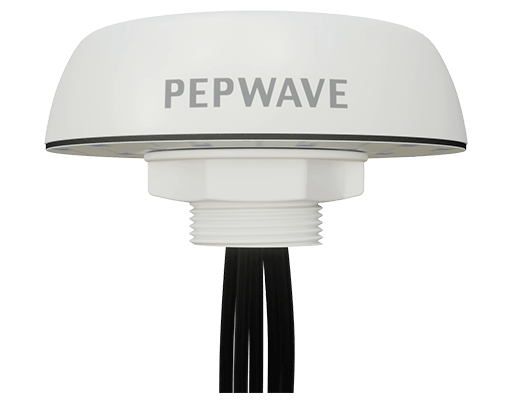
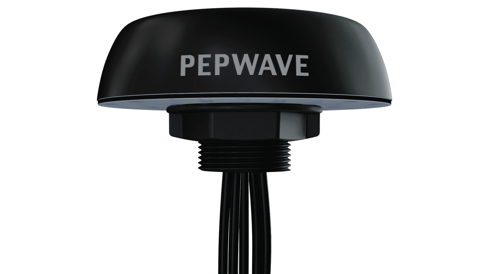
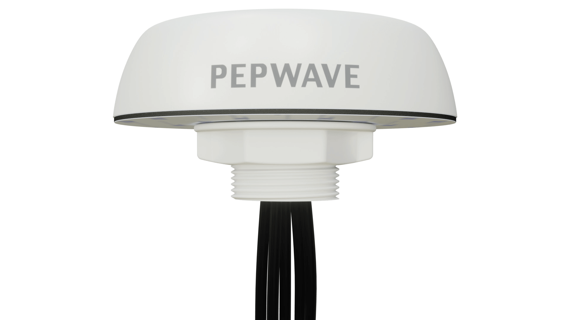
The Peplink Mobility 22G is a 5 in 1 antenna builtfor mobile applications. It supports 2×2 cellular MIMO for high bandwidth and solid reliability, dual-band (2.4GHz & 5GHz) Wi-Fi and GPS. It is also 5G ready and supports a wide range of global cellular frequencies. The GPS receiver is equipped with high gain LNA, making it ideal for location tracking.
The Mobility 22G has a solid housing made of UV stable plastic materials. Two color options are available (black and white) to fit different deployments. For easier installation, the antenna comes with different cable length options.
FEATURES
• 2×2 Cellular frequencies:
• 600-6000 MHz
• 2×2 Wi-Fi frequencies: 2400-2500 MHz & 5000-6000 MHz
• Durable and UV-stable housing
• Black or white color options
• IP68 rated
APPLICATIONS
• Mobile healthcare
• Transportation Connectivity
SPECIFICATIONS
• Antenna elements: 2 elements
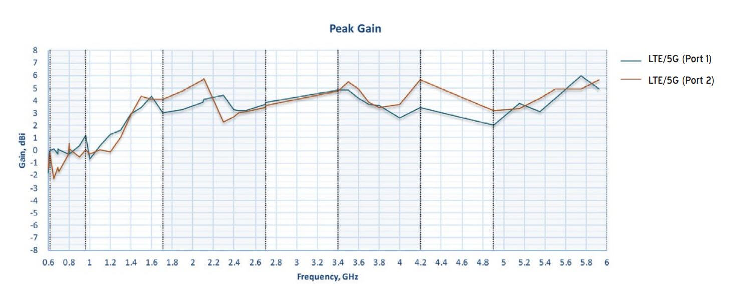
• Cellular frequencies: 1.2dBi: 617-960MHz, 5.7dBi: 1710-2700MHz, 5.6dBi: 3400-4200MHz, 6.0dBi: 5000-6000MHz
• Cellular bands: LTE bands B1 to B86 (except B31, B72, B73, B87, B88), 5G bands n1 to n99
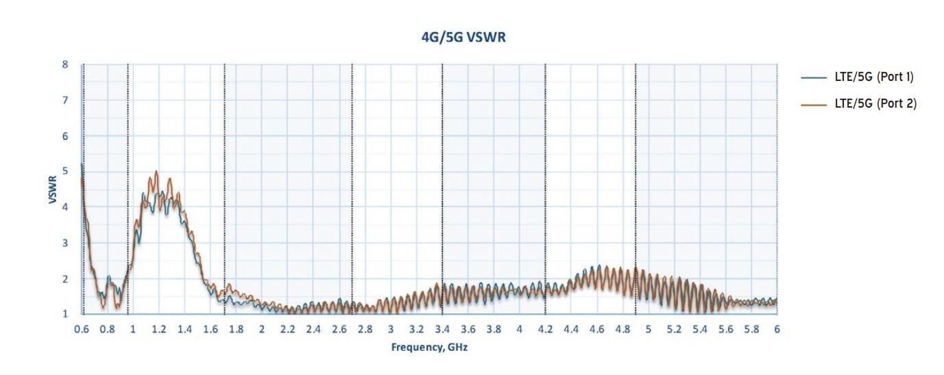
• VSWR: < 2.5 over 85% of the band
• Feed power handling: 10W
• Input impedance: 50 Ω
• Polarisation: Linear
• Ground plane: Not required#
Wi-Fi
• Antenna elements: 2 elements
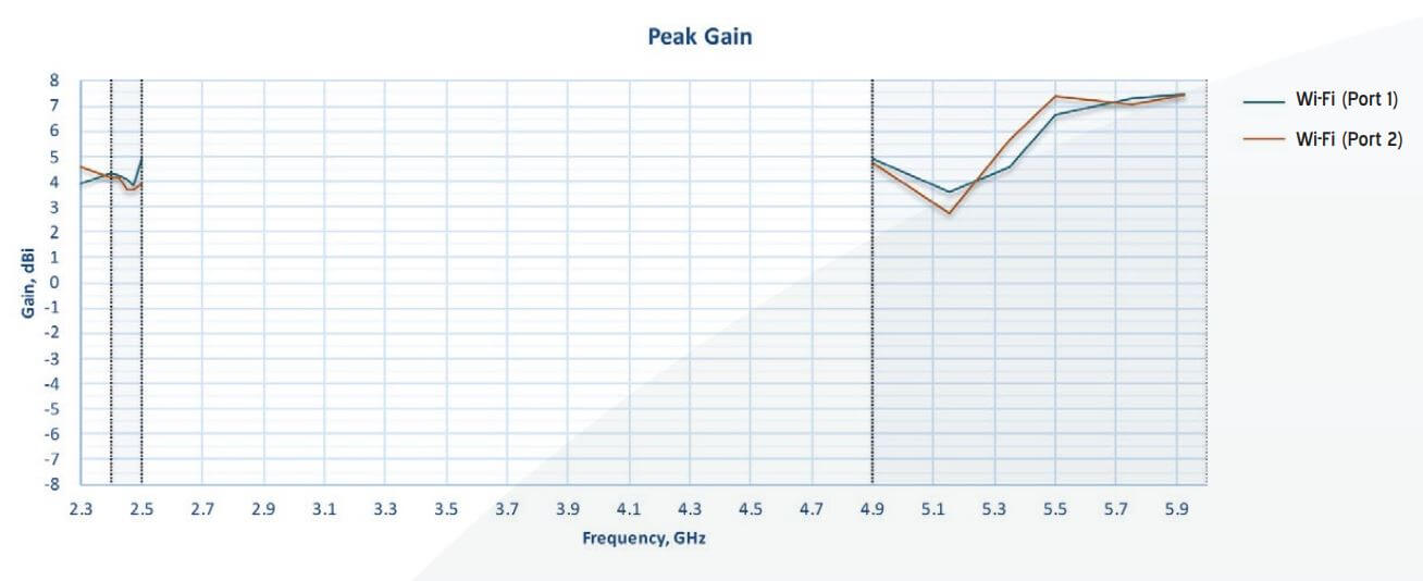
• Peak gain: 4.8dBi: 2400-2500MHz, 7.4dBi: 5000-6000MHz
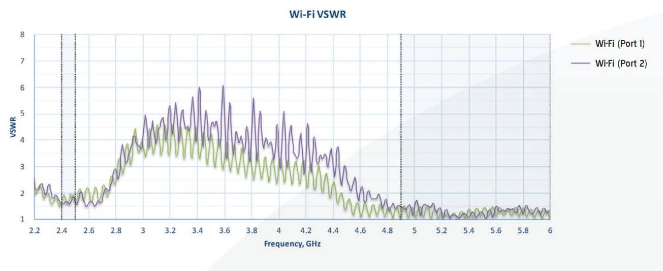
• VSWR: < 2.5
• Feed power handling: 10W
• Input impedance: 50 Ω
• Polarisation: Linear
GPS
• Frequency range: 1561-1602 MHz
• Peak gain: 0.5dBi: 1575MHz, 1.6dBi: 1602MHz
• VSWR: < 2 dB
• Output return loss: 10dB max
• Gain LNA: 28 ±3dB
• Noise figure: 1.5dB max at 3.3V
• Operating Voltage: 3.3V
• Power consumption: 8.5 ±2.5mA at 3.3V
Cable
• Type: CFD200
• Loss: 0.33 dB/m @ 900 MHz, 0.49 dB/m @ 2000 MHz, 0.55 dB/m @ 2500 MHz, 0.87 dB/m @ 5800 MHz
• Diameter: 0.2” / 5.0mm
• Jacket: Half matt PVC, UV resistant
• Termination: SMA male and RP-SMA male
• Type: RG-174
• Loss: 3.4 dB/m @ 1000 MHz, 4.9 dB/m @ 1800 MHz
• Diameter: 0.1″ / 2.7mm
• Jacket: Half matt PVC, UV resistant
• Termination: SMA male
Mounting
• Supported types: Panel, wall, pole
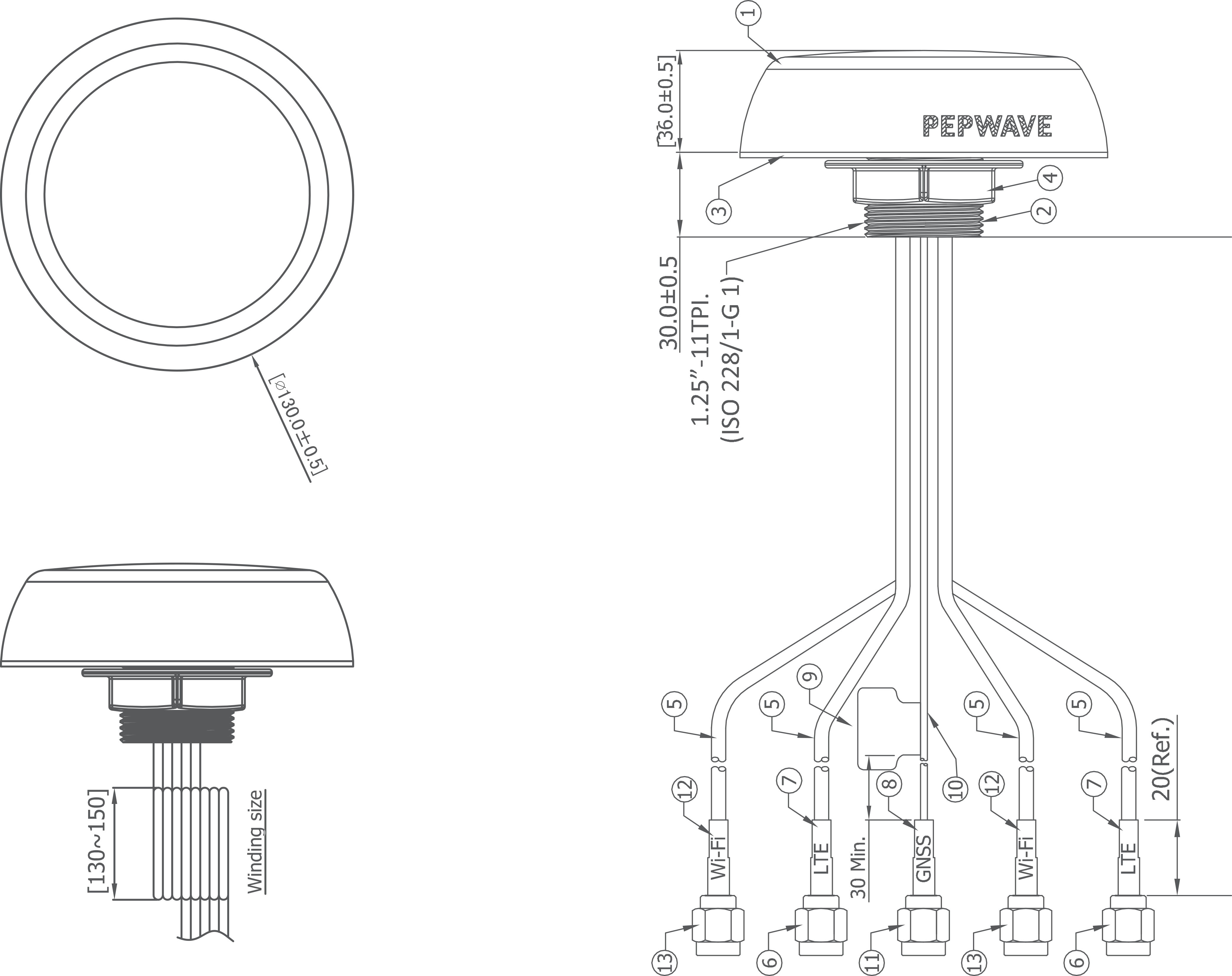
• Mounting hole: 1 11/16″ / 43mm
• Max panel thickness: 19/32″ / 15mm
Mechanical
• Product dimensions: Height: 1.42″ / 36mm (spigot not included) Diameter: 5.12″ / 130mm
• Packaged dimensions: 8.90″ x 8.46″ x 4.29″ / 226 x 215 x 109mm
• Radome material: UV stable PC+ABS
Package contents
Antenna: Mobility 22G
• Mounting: Mounting bracket, Wall/pole mount, Double sided 3M adhesive pad, Diameter: 5.08″ / 129mm, Thickness: 0.08″ / 2mm
Environmental, compliance
• Cable flammability: UL 758 (VW-1)
• Compliance: RoHS, REACH & WHEE
• Enclosure flammability: UL 94 HB
• IP rating: IP68
• Operating temperature: -40° – 80°C
• Storage temperature: -40° – 80°C
• Salt Spray: MIL-STD 810F/ASTM 8117
• UV resistance rating: UL 746C (F1, long-term UV exposure)
• Wind Survival: 220 km/h
# All measurements stated in this document were obtained without a ground plane.
ORDERING INFORMATION
MOBILITY 22G
EXTENSION CABLE
TECHNICAL DRAWING
Index
LTE/5G ANTENNA VSWR
Wi-Fi ANTENNA VSWR
LTE/5G ANTENNA GAIN
WI-FI ANTENNA GAIN
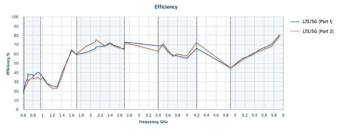
LTE/5G ANTENNA EFFICIENCY
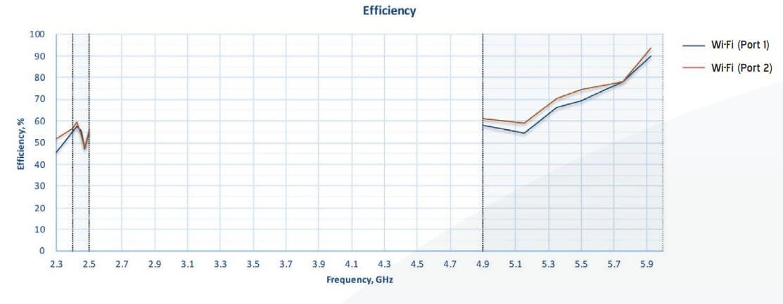
WI-FI ANTENNA EFFICIENCY
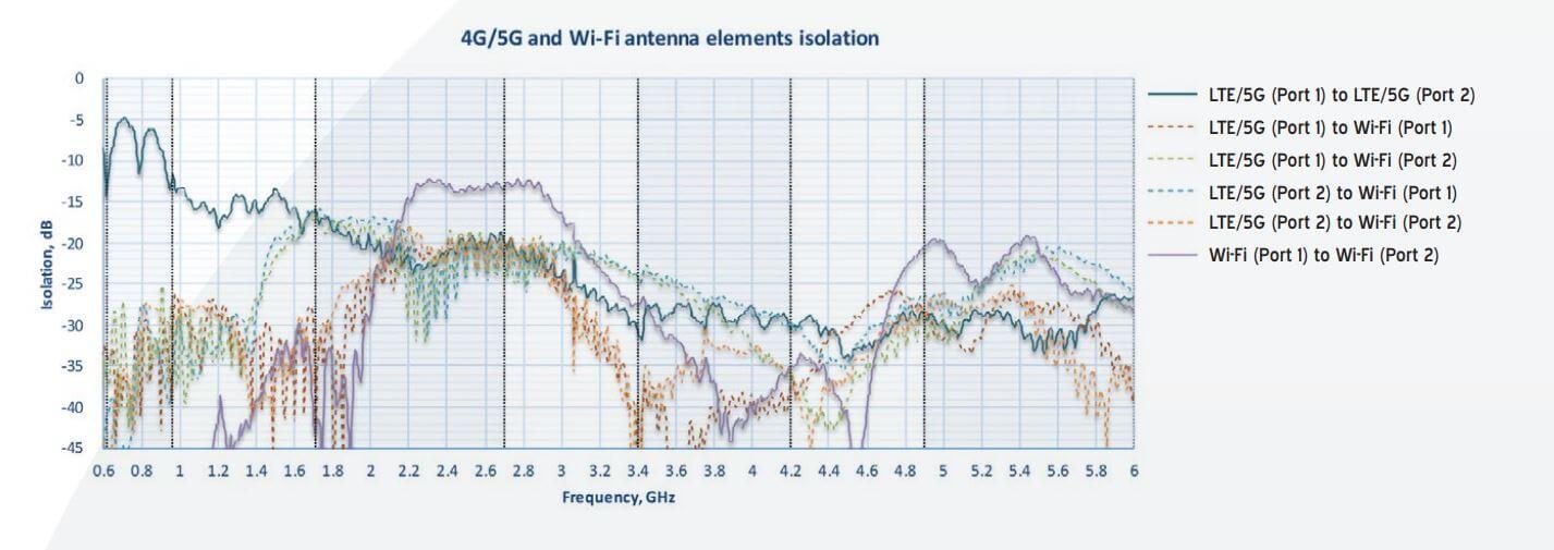
ANTENNA ISOLATION
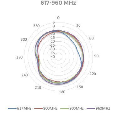
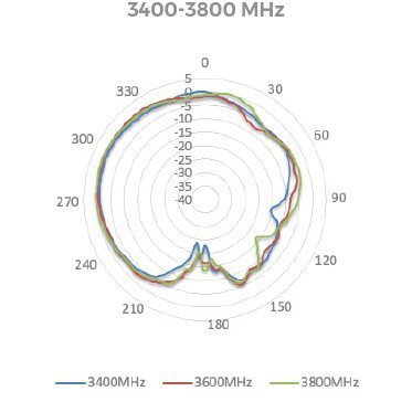
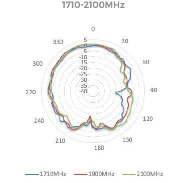
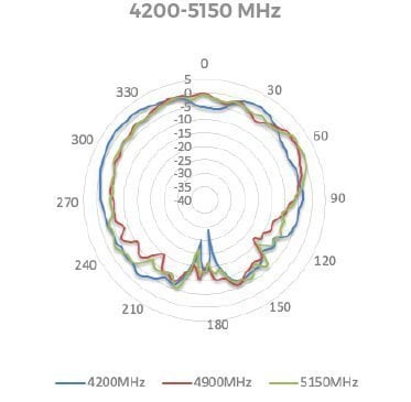
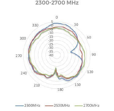
LTE/5G ANTENNA RADIATION PATTERNS (AZIMUTH)
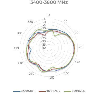
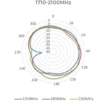
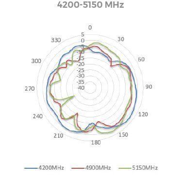
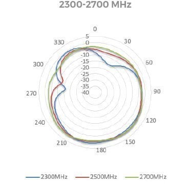
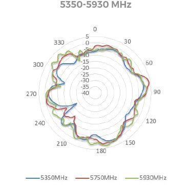
LTE/5G ANTENNA RADIATION PATTERNS (ELEVATION 1)
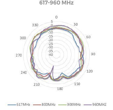
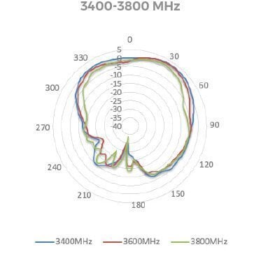
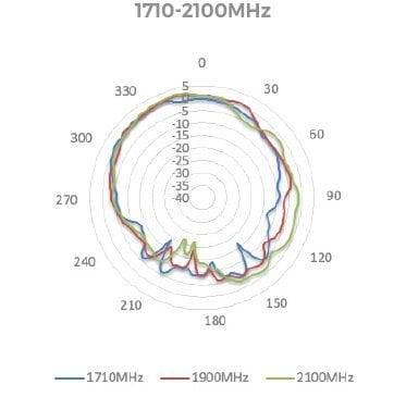
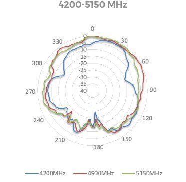
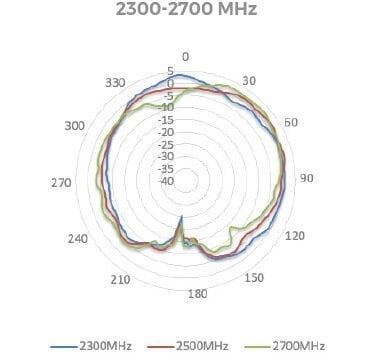
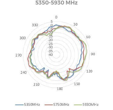
LTE/5G ANTENNA RADIATION PATTERNS (ELEVATION 2)
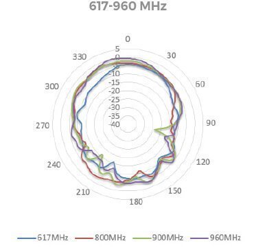
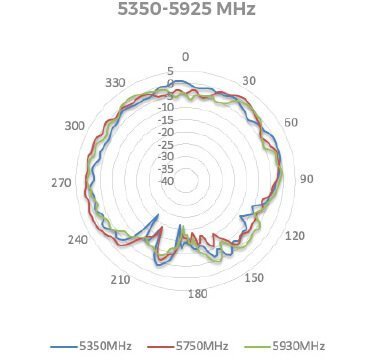
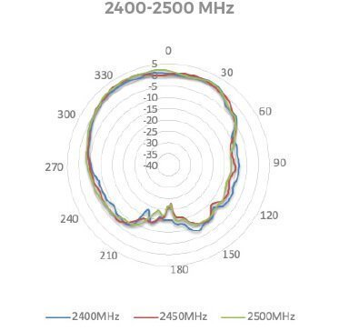
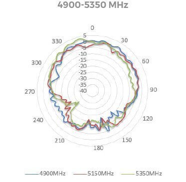
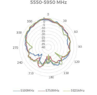
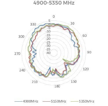
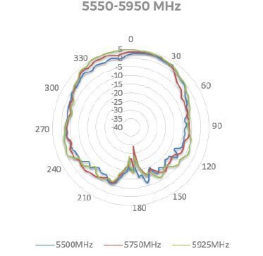
WI-FI ANTENNA RADIATION PATTERNS (AZIMUTH)
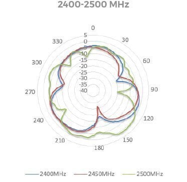
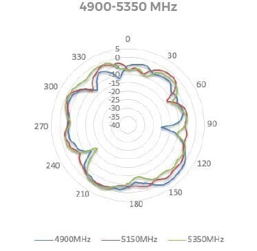
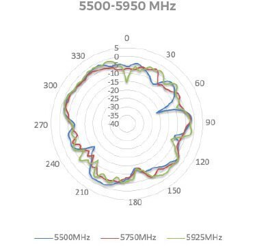
WI-FI ANTENNA RADIATION PATTERNS (ELEVATION 1)
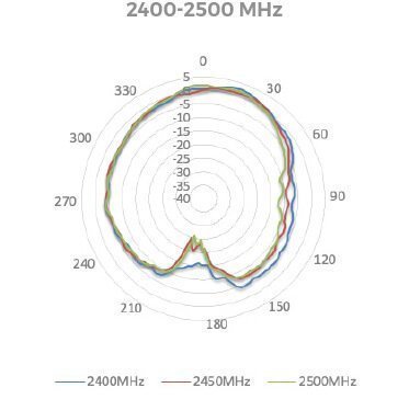
WI-FI ANTENNA RADIATION PATTERNS (ELEVATION 2)
PANEL MOUNT INSTALLATION RECOMMENDATION
Notes
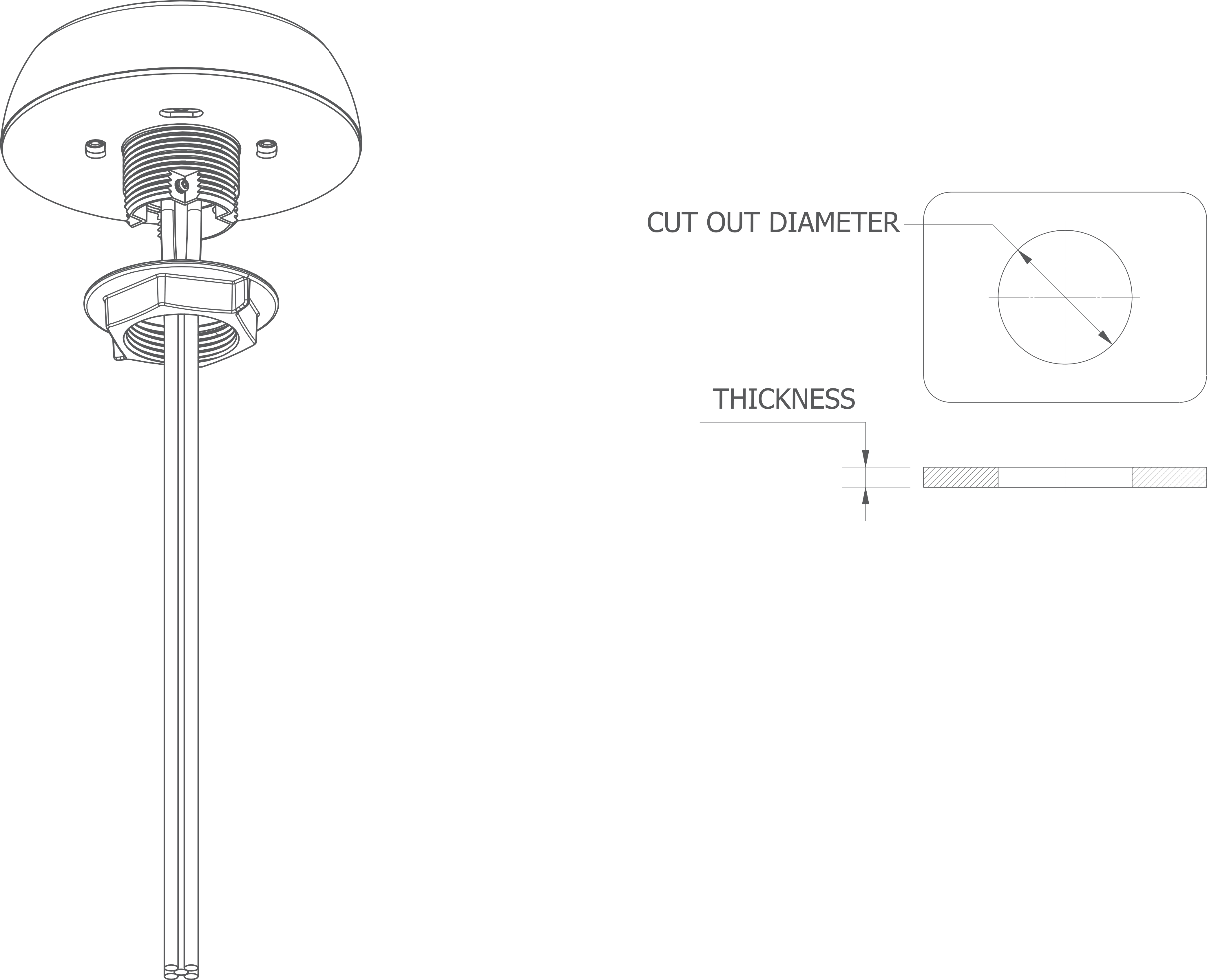
• Cover panel surface to protect the paint work. When drilling a hole, start with a small one, then increase it.
• Cut out diameter – 1.7 in. / 43 mm Maximum allowed panel thickness – 15 mm
• After a drill clean up the surface and apply some paint around the hole to prevent corrosion. Attach the antenna.
POLE MOUNT INSTALLATION RECOMMENDATION
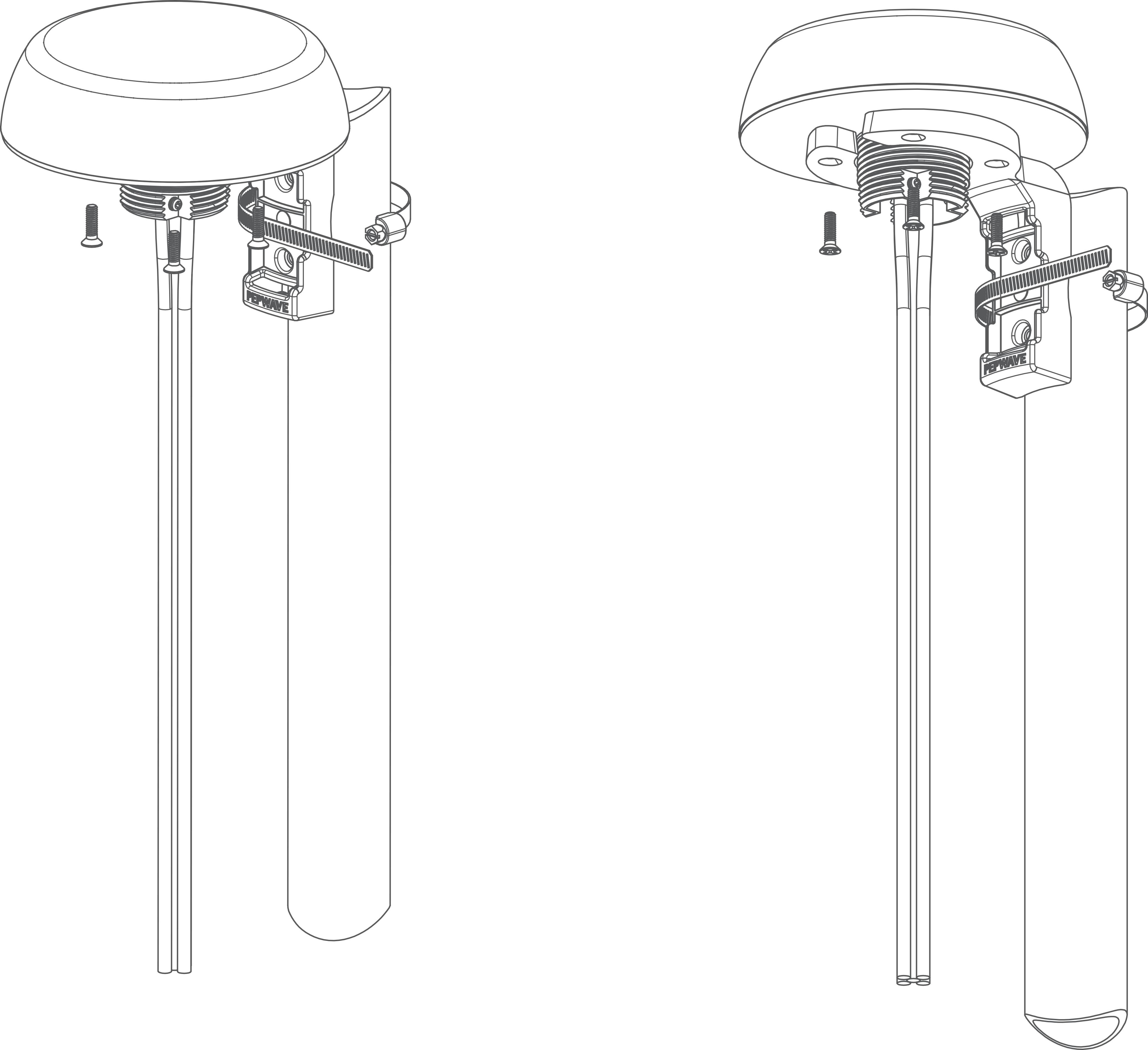
HORIZONTAL POLE MOUNT INSTALLATION RECOMMENDATION
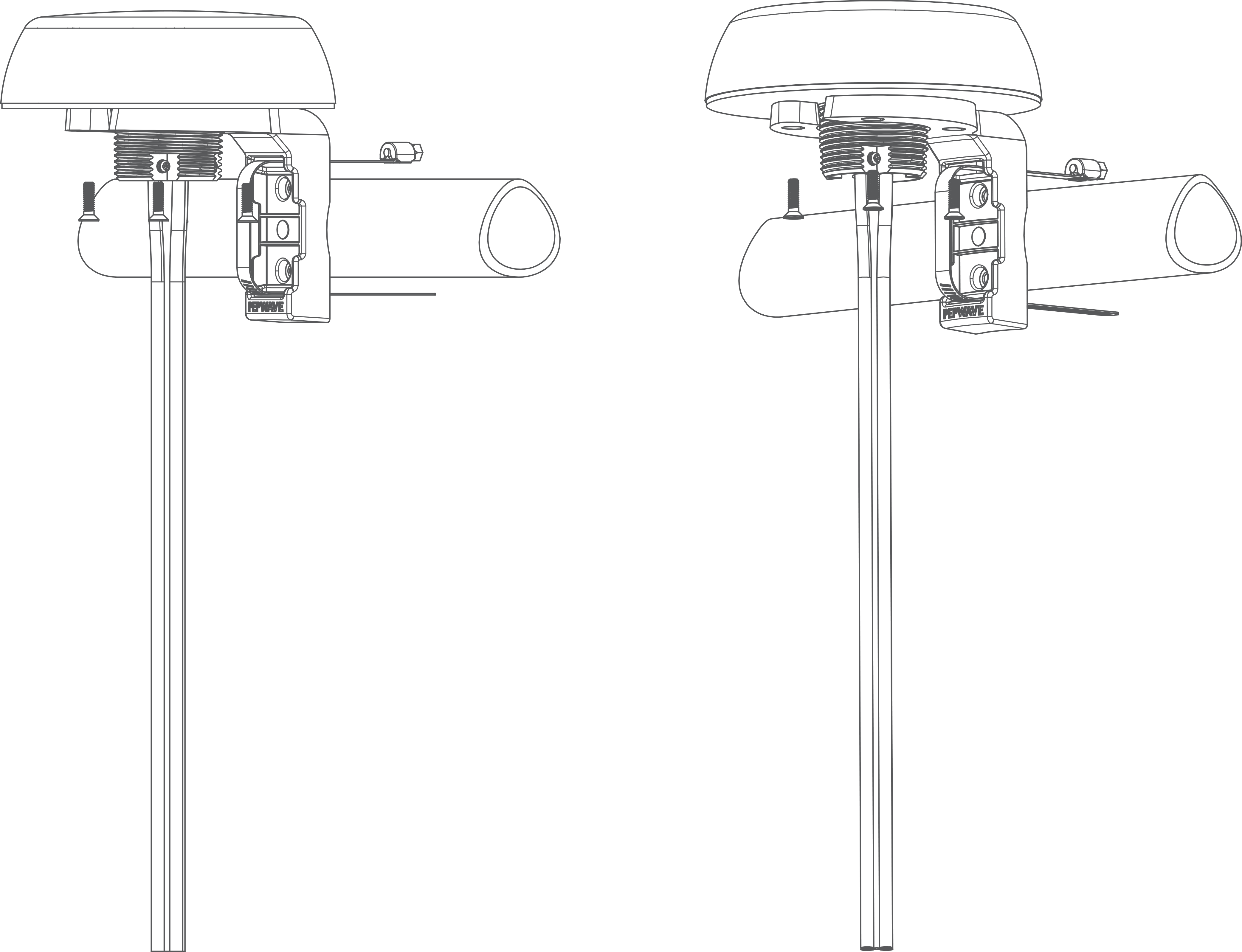
WALL MOUNT INSTALLATION RECOMMENDATION

WHY PEPLINK?
• Industry leader in both ISP & Data Bonding across multiple technology platforms
• Reliable hardware from entry level professional equipment through to advanced Enterprises solutions
• Worldwide supported and local support here in Australia by fully trained technicians
• Reliable and secure redundancy paths for mission critical sites
• Designed for maximum possible business uptime
This demonstrates to Rising Connection that you will have the Quality, Reliability and Product Support.

